TOPIC: DC CIRCUIT FUNDAMENTALS
SUBTOPICS: Electrical Quantities and Definitions, Ohm’s Law and Current Flow
SPECIFIC OUTCOMES:
1. Define electromotive force (EMF), potential difference (PD), and voltage, and state their SI units.
2. Define current, charge, resistance, conductance, resistivity, and conductivity with SI units.
3. Define electrical power and energy with SI units and relevant formulas.
4. Explain the difference between EMF and potential difference.
5. State five differences between resistance and resistivity.
6. State Ohm’s law and derive the equation V = I × R.
7. Explain with the aid of a diagram the flow of current in a circuit and state its SI units.
8. Calculate current, voltage, and resistance using Ohm’s law in simple circuits.
1. INTRODUCTION
Direct Current (DC) circuits are fundamental to understanding how electricity works. In this unit, we will explore the basic electrical quantities that describe how current flows, why it flows, and what opposes its flow. We will also learn about Ohm's Law, a crucial relationship between voltage, current, and resistance, and apply it to solve problems in simple DC circuits. Understanding these fundamentals is essential for further studies in electronics and electrical engineering.
2. CORE CONCEPTS
2.1 Electrical Quantities and Definitions
To understand DC circuits, we must first define the key quantities involved:
Charge (Q)
Charge is a fundamental property of matter that experiences a force when placed in an electromagnetic field. It is carried by subatomic particles like electrons (negative charge) and protons (positive charge). The SI unit of charge is the Coulomb (C). One Coulomb is approximately the charge of 6.24 × 10¹⁸ electrons.
Current (I)
Current is defined as the rate of flow of electrical charges. In a conductor, this flow is typically due to the movement of free electrons. For current to flow, electrons move through the wire, transmitting the current. The SI unit of current is the Ampere (A). One Ampere is equivalent to one Coulomb of charge flowing past a point in one second.
The formula for calculating current (I) with charge (Q) and time (t) is:
I = Qt
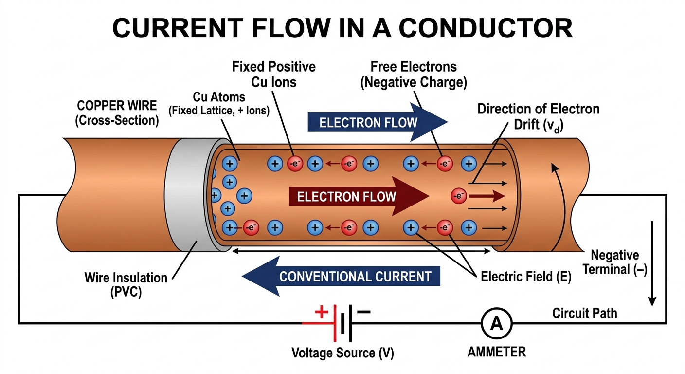 |
CURRENT FLOW IN A CONDUCTOR |
Electromotive Force (EMF, E or ε)
Electromotive force (EMF) is the energy supplied by a source (like a battery or generator) per unit charge to drive current around a complete circuit. It is the maximum potential difference that a source can provide when no current is flowing (open circuit). The SI unit of EMF is the Volt (V). One Volt is equivalent to one Joule of energy per Coulomb of charge (1 V = 1 J/C).
The formula for calculating EMF (E) with energy (Work done, W) and charge (Q) is:
E = WQ
Potential Difference (PD, V)
Potential difference (PD), often simply called voltage, is the work done or energy converted from electrical to other forms (e.g., heat, light) per unit charge as charge moves between two points in a circuit. It represents the "push" or "pressure" that drives current through a component. The SI unit of potential difference is also the Volt (V).
The formula for calculating potential difference (V) with energy (W) and charge (Q) is:
V = WQ
Worked Example 1: Calculating Current
If 480 Coulombs of charge flow through a wire in 4 minutes, calculate the current flowing through the wire.
Solution
| Given: |
Q = 480 C, t = 4 minutes |
| Find: |
I = ? |
| Convert: |
t = 4 minutes × 60 seconds/minute = 240 s |
| Formula: |
I = Qt |
| Substitute: |
I = 480 C240 s |
| Answer: |
I = 2 A |
Worked Example: Calculating current
Worked Example 2: Calculating Electromotive Force (EMF)
A battery performs 6.8 kJ of work to move 850 C of charge through a complete circuit. Calculate the electromotive force (EMF) of the battery.
Solution
| Given: |
W = 6.8 kJ, Q = 850 C |
| Find: |
E = ? |
| Convert: |
W = 6.8 kJ × 1000 J/kJ = 6800 J |
| Formula: |
E = WQ |
| Substitute: |
E = 6800 J850 C |
| Answer: |
E = 8 V |
Worked Example: Calculating Electromotive Force
Worked Example 3: Calculating Potential Difference
2.1 kJ of energy is converted when 420 Coulombs of charge pass through a light bulb. What is the potential difference across the bulb?
Solution
| Given: |
W = 2.1 kJ, Q = 420 C |
| Find: |
V = ? |
| Convert: |
W = 2.1 kJ × 1000 J/kJ = 2100 J |
| Formula: |
V = WQ |
| Substitute: |
V = 2100 J420 C |
| Answer: |
V = 5 V |
Worked Example: Calculating Potential Difference
✅ Check Your Understanding
Pause here. Let learners attempt these before moving on.
| 1. Quick Recall [1 mark] |
State the SI unit for electric charge and electric current. |
| 2. Apply the Concept [2-3 marks] |
A current of 0.5 A flows through a circuit for 10 seconds. Calculate the total charge that passes through the circuit. |
| 3. Misconception Check |
True or False: Electromotive force (EMF) and potential difference (PD) are always the same value in any given circuit. Justify your answer. |
Answers
1. The SI unit for electric charge is Coulomb (C), and for electric current is Ampere (A).
2. Given: I = 0.5 A, t = 10 s
Formula: Q = I × t
Substitute: Q = 0.5 A × 10 s
Answer: Q = 5 C
3. False. While both are measured in Volts, EMF is the total energy supplied by the source per unit charge (when no current flows), while PD is the energy converted per unit charge across a component in the circuit (when current flows). EMF is typically higher than the PD across any single external component due to internal resistance of the source.
2.2 Resistance, Conductance, Resistivity, and Conductivity
Resistance (R)
Resistance is the opposition to the flow of electric current in a circuit. Materials that offer high resistance are called insulators, while those offering low resistance are called conductors. A resistor is a device specifically designed to introduce resistance into a circuit. A rheostat is an adjustable resistor used to control current by varying its resistance. The SI unit of resistance is the Ohm (Ω).
Factors Affecting Resistance:
The resistance of a conductor depends on four main factors:
1. Length (L): Resistance is directly proportional to the length of the conductor. A longer wire has more resistance.
2. Cross-sectional Area (A): Resistance is inversely proportional to the cross-sectional area of the conductor. A thicker wire has less resistance.
3. Type of Material: Different materials have different inherent abilities to conduct electricity. For example, copper has lower resistance than iron for the same dimensions.
4. Temperature: For most metallic conductors, resistance increases with increasing temperature.
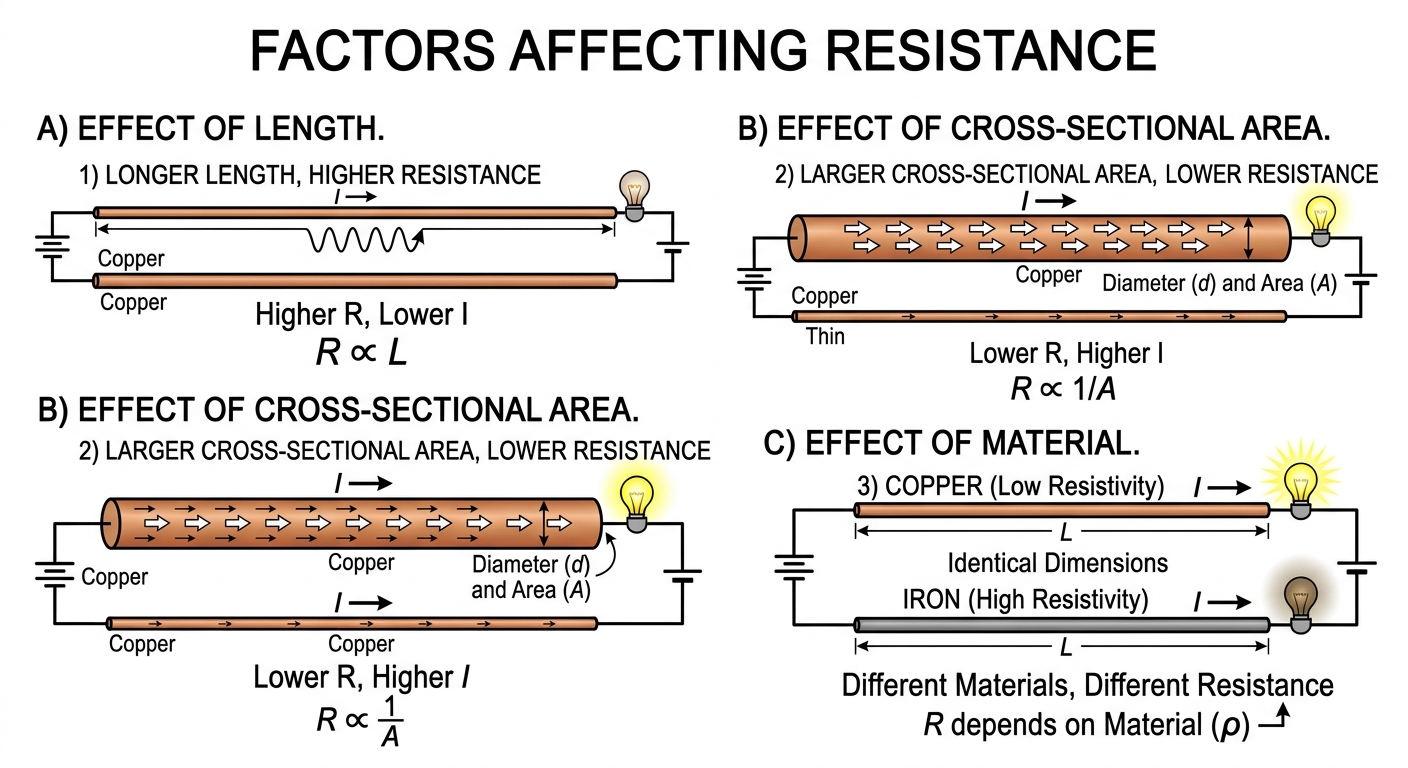 |
FACTORS AFFECTING RESISTANCE |
Conductance (G)
Conductance is the reciprocal of resistance. It is a measure of how easily electric current flows through a material. The SI unit of conductance is the Siemens (S), or sometimes the mho (Ω-1).
Formula: G = 1R
Resistivity (ρ)
Resistivity is an intrinsic property of a material that quantifies how strongly it resists electric current. Unlike resistance, which depends on the dimensions of the object, resistivity is a characteristic of the material itself. The SI unit of resistivity is the Ohm-metre (Ωm).
The formula for resistance (R) in terms of resistivity (ρ), length (L), and cross-sectional area (A) is:
R = ρ LA
Conductivity (σ)
Conductivity is the reciprocal of resistivity. It is an intrinsic property of a material that quantifies how well it conducts electric current. The SI unit of conductivity is the Siemens per metre (S/m).
Formula: σ = 1ρ
✅ Check Your Understanding
Pause here. Let learners attempt these before moving on.
| 1. Quick Recall [1 mark] |
What is the primary function of a rheostat in an electrical circuit? |
| 2. Apply the Concept [2-3 marks] |
A wire has a resistance of 50 Ω. Calculate its conductance. |
| 3. Misconception Check |
Which statement is correct? A) Resistance is an intrinsic property of a material. B) Resistivity is an intrinsic property of a material. Explain why. |
Answers
1. The primary function of a rheostat is to vary or adjust the resistance in a circuit, thereby controlling the current flow.
2. Given: R = 50 Ω
Formula: G = 1R
Substitute: G = 150 Ω
Answer: G = 0.02 S
3. Statement B) is correct. Resistivity is an intrinsic property of a material, meaning it depends only on the material itself and its temperature, not its shape or size. Resistance, on the other hand, depends on the material, its length, and its cross-sectional area.
2.3 Electrical Power and Energy
Electrical Power (P)
Electrical power is defined as the rate at which electrical energy is consumed or converted into other forms of energy (e.g., heat, light, mechanical energy) in a circuit. The SI unit of electric power is the Watt (W). One Watt is equivalent to one Joule per second (1 W = 1 J/s).
The basic formula for electrical power is:
P = V × I
Where:
• P = Power (Watts, W)
• V = Voltage or Potential Difference (Volts, V)
• I = Current (Amperes, A)
Using Ohm's Law (which we will cover next), this formula can also be expressed as:
P = I2 × R
or
P = V2R
Electrical Energy (E or W)
Electrical energy is the total amount of work done by an electric current over a period of time. It is the product of power and time. The SI unit of energy is the Joule (J). However, for practical purposes (especially for household electricity consumption), electrical energy is often measured in kilowatt-hours (kWh).
The formula for electrical energy is:
E = P × t
Where:
• E = Electrical Energy (Joules, J)
• P = Power (Watts, W)
• t = Time (seconds, s)
Cost of Electricity:
The cost of electricity is calculated based on the amount of energy consumed (in kWh) and the cost per unit (kWh).
Cost = Power (kW) × Time (hours) × Cost per unit (K)
Worked Example 4: Calculating Power
A small heater operates at 12 V and draws a current of 2 A. Calculate the power of the heater.
Solution
| Given: |
V = 12 V, I = 2 A |
| Find: |
P = ? |
| Formula: |
P = V × I |
| Substitute: |
P = 12 V × 2 A |
| Answer: |
P = 24 W |
Worked Example: Calculating Electrical Power
Worked Example 5: Calculating Electrical Energy
Using the heater from the previous example (24 W), how much energy will it use if it runs for 5 minutes?
Solution
| Given: |
P = 24 W, t = 5 minutes |
| Find: |
E = ? |
| Convert: |
t = 5 minutes × 60 seconds/minute = 300 s |
| Formula: |
E = P × t |
| Substitute: |
E = 24 W × 300 s |
| Answer: |
E = 7200 J |
Worked Example: Calculating Electrical Energy
Worked Example 6: Calculating Cost of Electricity
If the cost of 1 unit (1 kWh) of electricity in Zambia is K 0.50, what is the cost of running a 2 kW electric fire for 6 hours?
Solution
| Given: |
P = 2 kW, t = 6 hours, Cost per unit = K 0.50 |
| Find: |
Total Cost = ? |
| Formula: |
Cost = Power (kW) × Time (hours) × Cost per unit (K) |
| Substitute: |
Cost = 2 kW × 6 hours × K 0.50/kWh |
| Answer: |
Cost = K 6.00 |
Worked Example: Calculating Cost of Electricity
✅ Check Your Understanding
Pause here. Let learners attempt these before moving on.
| 1. Quick Recall [1 mark] |
Define electrical power and state its SI unit. |
| 2. Apply the Concept [2-3 marks] |
An electric kettle is rated 240 V and 1000 W. Calculate the current it draws when operating correctly. |
| 3. Misconception Check |
True or False: Electrical energy is measured in Watts, while electrical power is measured in Joules. Justify your answer. |
Answers
1. Electrical power is the rate at which electrical energy is consumed or converted. Its SI unit is the Watt (W).
2. Given: V = 240 V, P = 1000 W
Formula: P = V × I → I = PV
Substitute: I = 1000 W240 V
Answer: I ≈ 4.17 A
3. False. Electrical power is measured in Watts (W), and electrical energy is measured in Joules (J) or kilowatt-hours (kWh). A common misconception is confusing the units of power and energy.
2.4 Differences Between EMF and Potential Difference
While both EMF and Potential Difference are measured in Volts, they represent different aspects of electrical circuits:
EMF vs. Potential Difference
| Electromotive Force (EMF) |
Potential Difference (PD) |
| It is the energy supplied by the source per unit charge to drive current around the entire circuit. |
It is the energy converted from electrical to other forms per unit charge as current flows through a component (e.g., resistor, bulb). |
| Exists even when no current is drawn from the source (open circuit). It is the maximum voltage a source can provide. |
Exists only when current flows through a component (closed circuit). It is the 'voltage drop' across a component. |
| It is the cause of current flow. |
It is an effect of current flow and resistance in a component. |
| Measured across the terminals of a source when no current is flowing (open circuit). |
Measured across the terminals of a component when current is flowing. |
| EMF is generally greater than the potential difference across any external component due to internal resistance of the source. |
PD across an external resistor is less than the EMF of the source if the source has internal resistance. |
Figure: Comparison of Electromotive Force and Potential Difference
2.5 Differences Between Resistance and Resistivity
Resistance vs. Resistivity
| Resistance (R) |
Resistivity (ρ) |
| 1. It is the opposition to the flow of electric current in a specific conductor. |
1. It is an intrinsic property of a material, indicating its inherent ability to oppose current flow. |
| 2. Depends on the dimensions (length and cross-sectional area) of the conductor, as well as the material and temperature. |
2. Does NOT depend on the dimensions (length or cross-sectional area) of the conductor; only on the material and temperature. |
| 3. Has SI unit of Ohm (Ω). |
3. Has SI unit of Ohm-metre (Ωm). |
| 4. Can be changed by altering the length or thickness of the wire. |
4. Cannot be changed by altering the length or thickness of the wire; it's a fixed property for a given material at a given temperature. |
| 5. Represented by the formula: R = V/I |
5. Represented by the formula: ρ = R × AL |
Figure: Five differences between Resistance and Resistivity
✅ Check Your Understanding
Pause here. Let learners attempt these before moving on.
| 1. Quick Recall [1 mark] |
State the SI unit for resistivity. |
| 2. Apply the Concept [2-3 marks] |
A copper wire of length 2 m and cross-sectional area 0.5 mm2 has a resistance of 0.068 Ω. Calculate the resistivity of copper. (Hint: Convert area to m2). |
| 3. Misconception Check |
A student claims that a 10 cm piece of copper wire has half the resistivity of a 20 cm piece of the same copper wire. Is this statement true or false? Justify your answer. |
Answers
1. The SI unit for resistivity is Ohm-metre (Ωm).
2. Given: L = 2 m, A = 0.5 mm2, R = 0.068 Ω
Convert Area: 0.5 mm2 = 0.5 × 10⁻⁶ m2
Formula: ρ = R × AL
Substitute: ρ = 0.068 Ω × (0.5 × 10-6 m2)2 m
Answer: ρ = 1.7 × 10⁻⁸ Ωm
3. False. Resistivity is an intrinsic property of the material and does not depend on the length or dimensions of the wire. Both pieces of copper wire, regardless of their length, will have the same resistivity at a given temperature. The student is confusing resistance with resistivity.
2.6 Ohm’s Law and Current Flow
Ohm’s Law
Ohm's Law states that the current flowing through a metallic conductor is directly proportional to the potential difference (voltage) across its ends, provided that the temperature and other physical conditions remain constant.
Mathematically, this relationship is expressed as:
V ∝ I
By introducing a constant of proportionality, which is resistance (R), we derive the equation:
V = I × R
Where:
• V = Potential Difference (Volts, V)
• I = Current (Amperes, A)
• R = Resistance (Ohms, Ω)
This formula can be rearranged to find any of the three quantities:
Key Formulas: Ohm's Law
| Ohm's Law |
V = I × R
→
I = VR
→
R = VI
|
V = voltage (V) | I = current (A) | R = resistance (Ω)
Figure: Ohm's Law formula and its rearrangements
Flow of Current in a Circuit
In a simple DC circuit, current flows from the positive terminal of the power source (e.g., battery) through the components to the negative terminal. This is known as conventional current flow. It's important to note that electrons, which are the actual charge carriers in metals, flow in the opposite direction (from negative to positive). For circuit analysis, we generally use conventional current.
For charges to flow through a circuit, two main conditions must be met:
1. A Closed Circuit: The circuit must form a complete loop, allowing charge to flow continuously from the source, through the components, and back to the source.
2. Potential Difference: There must be a potential difference (voltage) across the circuit, provided by a power source, to "push" the charges.
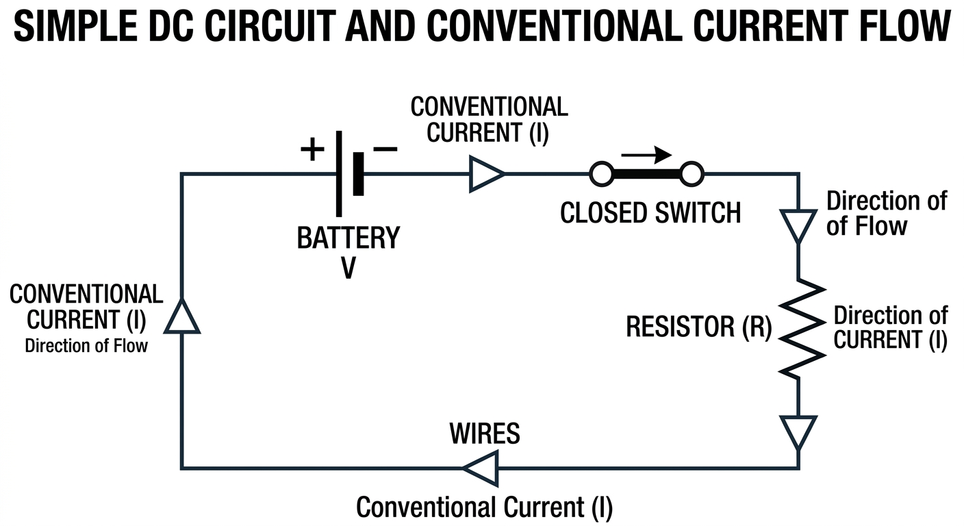 |
SIMPLE DC CIRCUIT AND CONVENTIONAL CURRENT FLOW |
Worked Example 7: Calculating Resistance
How many ohms of resistance must be present in a circuit that has a voltage of 120 V and a current of 10 A?
Solution
| Given: |
V = 120 V, I = 10 A |
| Find: |
R = ? |
| Formula: |
R = VI |
| Substitute: |
R = 120 V10 A |
| Answer: |
R = 12 Ω |
Worked Example: Calculating Resistance using Ohm's Law
Worked Example 8: Calculating Current
A circuit contains two 1.5 V batteries connected in series, and a bulb with a resistance of 3 Ω. Calculate the current flowing through the circuit.
Solution
| Given: |
Two 1.5 V batteries in series, R = 3 Ω |
| Find: |
I = ? |
| Total Voltage: |
Vtotal = 1.5 V + 1.5 V = 3.0 V |
| Formula: |
I = VR |
| Substitute: |
I = 3.0 V3 Ω |
| Answer: |
I = 1 A |
Worked Example: Calculating Current in a Simple Circuit
Worked Example 9: Calculating Voltage
A light bulb has a resistance of 4 Ω and a current of 2 A flowing through it. What is the voltage across the bulb?
Solution
| Given: |
R = 4 Ω, I = 2 A |
| Find: |
V = ? |
| Formula: |
V = I × R |
| Substitute: |
V = 2 A × 4 Ω |
| Answer: |
V = 8 V |
Worked Example: Calculating Voltage using Ohm's Law
✅ Check Your Understanding
Pause here. Let learners attempt these before moving on.
| 1. Quick Recall [1 mark] |
State Ohm's Law. |
| 2. Apply the Concept [2-3 marks] |
A resistor of 20 Ω is connected across a 12 V battery. Calculate the current flowing through the resistor. |
| 3. Misconception Check |
A student draws a circuit diagram showing current flowing from the negative terminal of a battery to the positive terminal. Is this representation correct for conventional current? Explain why. |
Answers
1. Ohm's Law states that the current flowing through a metallic conductor is directly proportional to the potential difference across its ends, provided that the temperature and other physical conditions remain constant.
2. Given: R = 20 Ω, V = 12 V
Formula: I = VR
Substitute: I = 12 V20 Ω
Answer: I = 0.6 A
3. False. For conventional current, the flow is defined from the positive terminal to the negative terminal of the battery. Electron flow is indeed from negative to positive, but conventional current is a historical convention still widely used in circuit analysis. The student is confusing conventional current with electron flow.
3. SUMMARY
This unit introduced the foundational concepts of DC circuits. We defined key electrical quantities such as charge (Coulomb), current (Ampere), electromotive force (Volt), potential difference (Volt), resistance (Ohm), conductance (Siemens), resistivity (Ohm-metre), and conductivity (Siemens per metre). We explored the differences between EMF and potential difference, and between resistance and resistivity. Finally, we stated and derived Ohm's Law (V = I × R) and applied it to calculate voltage, current, and resistance in simple circuits. Understanding these definitions and relationships is crucial for analyzing more complex electrical circuits.
4. ASSESSMENT QUESTIONS
1. Define the following terms and state their SI units:
a) Electric Charge [2 marks]
b) Electric Current [2 marks]
c) Electromotive Force (EMF) [2 marks]
d) Potential Difference (PD) [2 marks]
e) Resistance [2 marks]
f) Electrical Power [2 marks]
g) Electrical Energy [2 marks]
2. Explain the main difference between electromotive force (EMF) and potential difference (PD). Give an example where their values might differ. [3 marks]
3. State five differences between resistance and resistivity. [5 marks]
4. State Ohm's Law. [1 mark]
a) Derive the formula V = I × R from the proportionality relationship. [2 marks]
b) A torch bulb has a resistance of 8 Ω and operates with a current of 0.25 A. Calculate the voltage across the bulb. [2 marks]
5. With the aid of a labelled diagram, explain how current flows in a simple DC circuit. Indicate the direction of conventional current. [4 marks]
6. A heating element has a resistance of 30 Ω and is connected to a 240 V mains supply.
a) Calculate the current flowing through the heating element. [2 marks]
b) Calculate the power consumed by the heating element. [2 marks]
c) If the heater is used for 2 hours, calculate the electrical energy consumed in Joules. [3 marks]
7. A 1.5 A current flows through a 100 Ω resistor for 30 minutes.
a) Calculate the potential difference across the resistor. [2 marks]
b) Determine the total charge that passes through the resistor. [2 marks]
c) Calculate the electrical power dissipated by the resistor. [2 marks]
5. SOLUTIONS
1. a) Electric Charge: A fundamental property of matter that experiences a force in an electromagnetic field. SI unit: Coulomb (C).
b) Electric Current: The rate of flow of electrical charges. SI unit: Ampere (A).
c) Electromotive Force (EMF): The energy supplied by a source per unit charge to drive current around a complete circuit. SI unit: Volt (V).
d) Potential Difference (PD): The energy converted from electrical to other forms per unit charge as charge moves between two points in a circuit. SI unit: Volt (V).
e) Resistance: The opposition to the flow of electric current in a circuit. SI unit: Ohm (Ω).
f) Electrical Power: The rate at which electrical energy is consumed or converted. SI unit: Watt (W).
g) Electrical Energy: The total amount of work done by an electric current over a period of time. SI unit: Joule (J) or kilowatt-hour (kWh).
2. Main Difference: EMF is the energy supplied by a source per unit charge (total push available from the source, even on an open circuit), while PD is the energy converted per unit charge across a component (voltage drop across a load when current is flowing).
Example: A 12 V car battery has an EMF of 12 V. When it starts the engine, the actual potential difference across its terminals might drop slightly to, say, 11.5 V due to its internal resistance.
3.
Resistance vs. Resistivity
| Resistance (R) |
Resistivity (ρ) |
| 1. Opposition to current in a specific conductor. |
1. Intrinsic property of a material. |
| 2. Depends on length, area, material, and temperature. |
2. Depends only on material and temperature. |
| 3. Unit: Ohm (Ω). |
3. Unit: Ohm-metre (Ωm). |
| 4. Changes with conductor dimensions. |
4. Independent of conductor dimensions. |
| 5. Formula: R = V/I |
5. Formula: ρ = R × AL |
4. Ohm's Law: The current flowing through a metallic conductor is directly proportional to the potential difference across its ends, provided that the temperature and other physical conditions remain constant.
a) Derivation:
From Ohm's Law, V ∝ I.
Introducing a constant of proportionality, R (resistance), we get:
V = I × R
b) Given: R = 8 Ω, I = 0.25 A
Formula: V = I × R
Substitute: V = 0.25 A × 8 Ω
Answer: V = 2 V
5. |
SIMPLE DC CIRCUIT AND CONVENTIONAL CURRENT FLOW |
Explanation: In a simple DC circuit, current flows from the positive terminal of the battery, through the closed switch, then through the resistor (or bulb), and finally back to the negative terminal of the battery. This direction is called conventional current. For current to flow, the circuit must be closed (a complete loop) and there must be a potential difference (voltage) provided by the battery. The SI unit of current is the Ampere (A).
6. Given: R = 30 Ω, V = 240 V
a) Current (I):
Formula: I = VR
Substitute: I = 240 V30 Ω
Answer: I = 8 A
b) Power (P):
Formula: P = V × I
Substitute: P = 240 V × 8 A
Answer: P = 1920 W
c) Electrical Energy (E):
Given: P = 1920 W, t = 2 hours
Convert time: t = 2 hours × 3600 seconds/hour = 7200 s
Formula: E = P × t
Substitute: E = 1920 W × 7200 s
Answer: E = 13 824 000 J
7. Given: I = 1.5 A, R = 100 Ω, t = 30 minutes
a) Potential Difference (V):
Formula: V = I × R
Substitute: V = 1.5 A × 100 Ω
Answer: V = 150 V
b) Total Charge (Q):
Convert time: t = 30 minutes × 60 seconds/minute = 1800 s
Formula: Q = I × t
Substitute: Q = 1.5 A × 1800 s
Answer: Q = 2700 C
c) Electrical Power (P):
Formula: P = I2 × R (or P = V × I)
Substitute: P = (1.5 A)2 × 100 Ω = 2.25 × 100 Ω
Answer: P = 225 W
6. COMMON DIFFICULTIES & MISCONCEPTIONS
• Confusing EMF and PD: Learners often use these terms interchangeably, not understanding that EMF is the total energy supplied by the source (open circuit voltage), while PD is the energy converted across a component (voltage drop in a closed circuit).
• Confusing Resistance and Resistivity: Students may think resistivity changes with the length or thickness of a wire, confusing it with resistance.
• Direction of Current: Misconception between conventional current (positive to negative) and electron flow (negative to positive).
• Units: Incorrectly using units (e.g., Watts for energy instead of Joules, or Joules for power instead of Watts).
• Ohm's Law Application: Difficulty rearranging Ohm's Law formula (V = I × R) to solve for different variables, or forgetting to convert units (e.g., minutes to seconds).
• Factors Affecting Resistance: Not remembering all four factors (length, area, material, temperature) or misinterpreting their relationships (e.g., thinking thicker wire has more resistance).
7. QUICK REFERENCE SUMMARY
Key Terms & Formulas: DC Circuit Fundamentals
| Charge (Q) |
Fundamental property of matter. Unit: Coulomb (C). |
| Current (I) |
Rate of flow of charge. Unit: Ampere (A). Formula: I = Qt |
| EMF (E) |
Energy supplied by source per unit charge. Unit: Volt (V). Formula: E = WQ |
| PD (V) |
Energy converted per unit charge across component. Unit: Volt (V). Formula: V = WQ |
| Resistance (R) |
Opposition to current flow. Unit: Ohm (Ω). Factors: length, area, material, temperature. |
| Resistivity (ρ) |
Intrinsic property of material. Unit: Ohm-metre (Ωm). Formula: ρ = R × AL |
| Power (P) |
Rate of energy conversion. Unit: Watt (W). Formula: P = V × I |
| Energy (E) |
Total work done. Unit: Joule (J) or kWh. Formula: E = P × t |
| Ohm's Law |
V = I × R → I = VR → R = VI |
Figure: Summary of key terms and formulas